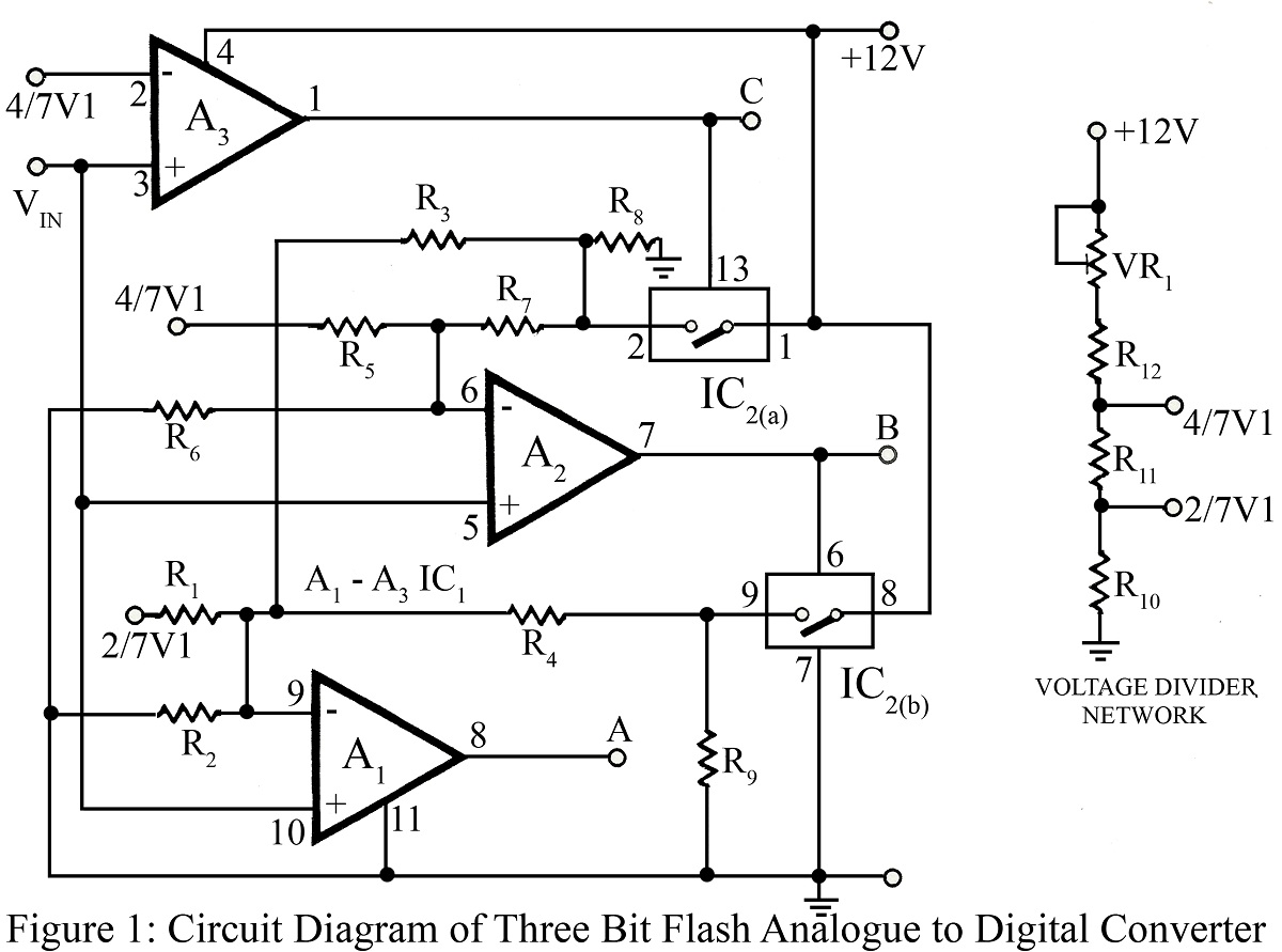
- SIMPLE ANALOG TO DIGITAL CONVERTER SCHEMATIC HOW TO
- SIMPLE ANALOG TO DIGITAL CONVERTER SCHEMATIC PDF
- SIMPLE ANALOG TO DIGITAL CONVERTER SCHEMATIC SERIAL
- SIMPLE ANALOG TO DIGITAL CONVERTER SCHEMATIC SOFTWARE
The result will be an unsigned number between 0 and 2 resolution, indicating where the input voltage is located in the span between ground and the reference voltage Differential Mode In differential mode the measured value is the difference between two inputs. The voltage span between 0 V and the selected reference is divided in small steps according to the selected resolution.
SIMPLE ANALOG TO DIGITAL CONVERTER SCHEMATIC SERIAL
If high ADC accuracy is needed, it is advisable to not use any of the unused ADC input pins for noise inducing activities such as serial communication Single Ended Mode In single ended mode the input signal is measured with ground as the lower reference.

The ADC input signals are shielded fairly well against other noisy signals within the EFM32. The DIFF bit in ADCn_SINGLECTRL or ADCn_SCANCTRL enables differential mode. The lowest channel number is the positive differential input. Two neighbouring inputs are used in differential mode, for instance channel 0 and channel 1 is one differential pair, channel 2 and channel 3 another. 2.2 Input Selection The 8 external inputs can either be selected as single ended inputs, or combined to allow for differential inputs. The resulting ADC clock should be between 32 khz and 13 MHz. Any factor between 1 and 128 can be chosen by writing to a value between 0 and 127 the PRESC bits in ADCn_CTRL. Analog to Digital Converter Overview ADCn_STATUS ADCn_CTRL ADCn_CMD ADCn_SINGLECTRL ADCn_SCANCTRL ADCn_SINGLEDATA ADCn_SCANDATA Oversampling filter HFPERCLK ADCn Prescaler ADC_CLK Sequencer Result buffer ADCn_CH0 ADCn_CH1 ADCn_CH2 ADCn_CH3 ADCn_CH4 ADCn_CH5 ADCn_CH6 ADCn_CH7 Temp V DD/ Control SAR V DD V SS V ref/ 2 DAC0 DAC1 V DD 1.25 V 2.5 V 5 V differential 2x(VDD- VSS) an0021_revģ 2 General Operation.the world's most energy friendly microcontrollers 2.1 Clock Selection The ADC clock is supplied by an ADC-clock prescaler which divides the peripheral clock (HFPERCLK) by a selectable factor between 1 and 128. 2) illustrates the internal connections of the inputs, reference selection and registers. For sampling frequencies below a couple of kilohertz, this is the best way to do low power ADC sampling.
SIMPLE ANALOG TO DIGITAL CONVERTER SCHEMATIC SOFTWARE
For extremely low power periodic ADC sampling, a software example which enter EM2 between each ADC sample is also included. Offset and Gain Calibration of the ADC is also described and included in the software examples. Software examples of ADC operation both with DMA and PRS are included. In addition, advanced features and power saving techniques are described. This application note shows general operation and usage of the ADC.

The ADC can be clocked at different speeds, and run at different warm-up modes to reduce the energy consumption even further. With the help of PRS and DMA, the ADC can operate without CPU intervention, minimizing current consumption or allow the core to do other work. The integrated input mux can select ADC-input from 8 external pins or 6 internal signals.

The maximum resolution is 12 bits, and one million samples per second can be achieved at this resolution.
SIMPLE ANALOG TO DIGITAL CONVERTER SCHEMATIC PDF
This application note includes: This PDF document Source files (zip) Example C-code Multiple IDE projectsĢ 1 Analog to Digital Converter 1.1 Introduction.the world's most energy friendly microcontrollers The EFM32 ADC is a Successive Approximation Register (SAR) architecture. Calibration routines for offset and gain are also included. Many aspects of the ADC, including inputs, references and the different operating modes are described.
SIMPLE ANALOG TO DIGITAL CONVERTER SCHEMATIC HOW TO
1 Analog to Digital Converter AN Application Note Introduction This application note describes how to use the EFM32 Analog to Digital Converter to convert an analog input voltage to a digital value.


 0 kommentar(er)
